
St Pancras Build instructions
Intro
Please note where all items were packed. They should be returned to the same place. KEEP ALL PACKAGING for return journey.
If using the standard option, assemble all truss after St Pancras is finished.
If using the extended option (overhead truss as well), assemble top part first, then build deck and St Pancras underneath. Add lower rails once the staging is complete.
2 people are required to assemble this model, who are able to lift a large and heavy model. It is not possible to complete the build with only one person.
The deck is very strong. If needs be, you can kneel or stand on it.
Before removing anything from the flightcases, be sure to watch this video of how to unpack the sections from the case. Failure to use this method WILL result in damage.
Deck
1. DO NOT cut the strapping around the flightcases.
2. Open all flightcases by turning the catches 90 degrees anticlockwise and place lids on top of flightcases. See below for storage locations of large case
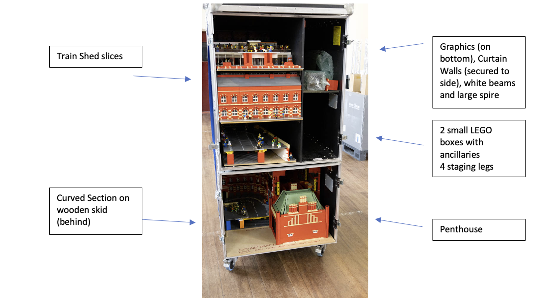
3. Remove 2 small LEGO boxes from top right side of larger flight case and put to one side. From behind these, remove 4 base sections of plinth from top right part of larger case.
4. Lay out these sections where St Pancras is to be built. These will expand to a 1 meter x 2 meter size each. PLEASE NOTE: It will not be possible to move the model once it is built. The 4 sections work width-wise across the model as shown below and the protruding pins should be UPWARDS. For now, place them loosely next to each other.
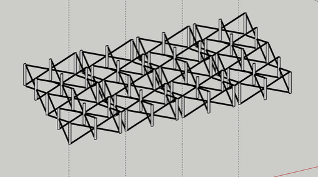
5. Place the 4 deck sections on top of each of the leg sections. The pins from the legs should match into holes in the deck.
a. Take note of the edge with Velcro – this should always face outwards.
b. The two end sections will be obvious where to place. Place the 2 centre sections so that the protruding jaws all face in the same direction (towards one of the short sides of the assembled deck), it doesn’t matter which.
c. If the deck sections do not easily fit over the pins, it is possible they may not have been properly unlocked. See point 8 below.
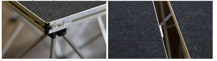
6. Using the hex key provided, make a quarter turn to secure each corner of each board. The holes for the hex keys are near the corners – look carefully as they are hard to see in the black carpet.
Note that if the floor is not level, you may need shims (not provided)
7. Mate the first two deck sections together – the jaws should slide into the groove on the next deck. Make sure the decks are flush against each other.
8. Again, using the Allen key, make a clockwise turn to secure the decks together. The hole for the hex key is directly above where the jaws are.
9. Repeat for the remaining deck sections.
10. Replace Allen key in flight case.
11. Check position is accurate, bearing in mind interpretation. This is the last time you can move the model.
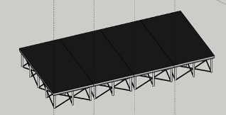
Deck assembly is complete.
St Pancras
Please note: The St Pancras model is not 100% glued. It is fragile and should be treated as such.
· ALWAYS lift sections with two people
· ALWAYS make sure you know where the section is going to be put down before you lift it.
· Many of the fittings in the flight cases are very tight – there is very little tolerance by design. The pieces do fit though. When removing or replacing sections make sure that they are 100% flat, level and straight.
· When removing sections from the case DO NOT LIFT them out. This will cause the base to bend.
Simply pull the section to slide horizontally completely out of the case. As it comes out of the case, support the weight until it is completely removed. Now lift straight up;
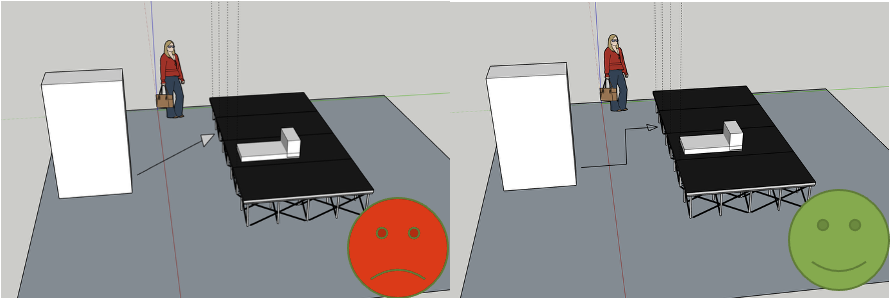
You will find it easiest to follow these instructions.
1. Place the flight cases to one side of the deck – about 1.5 meters away. This will give you room to remove the sections, lift them, then place them down. Make sure you can stand between the cases.
2. Engage the breaks on the flight cases.
3. Start with the straight part of the hotel. This is stored in the bottom of the thinner case.
4. Using two people, slide the hotel out of the bottom of the case. Do not lift it, simply slide the hotel forwards until it is free of the case. Then, lift it up and place it on the deck. The model is attached to the wooden (unpainted MDF) base. Do not try to remove it.
5. Slide the hotel along the deck into position.
a. The front of the hotel has 3 gables and 3 bay windows. Place the hotel so that the front of the building faces towards one of the short ends of the deck.
b. The hotel should be situated so that the rear of the building is along the joint line from one end section of staging to the next
c. The space for the clock tower should be towards the long side of the deck. It should be approximately 15cm from the edge of the deck.
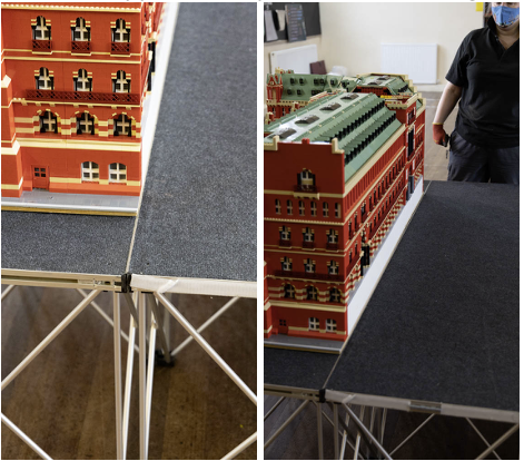
6. Remove any items stored inside this part of the hotel. Leave the foam inside the building.
7. Next, unpack and put to one side the upper part ‘penthouse’ of the hotel. This is stored in the bottom of the wider flight case – at the front.
8. Simply lift this section out from where it is stored in the flight case and put on the deck in front of the hotel. You can place your fingers into the arches for ease of lift.
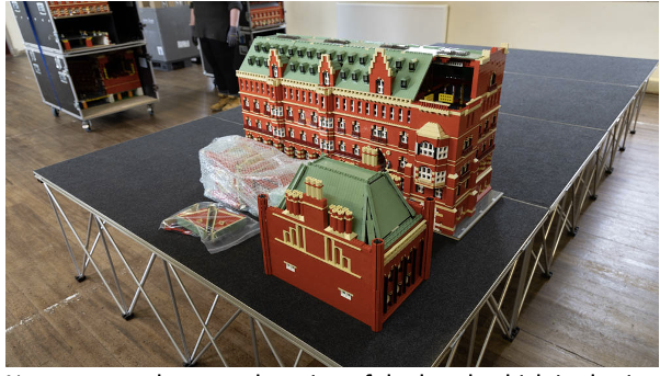
9. Now remove the curved section of the hotel, which is also in the bottom part of the wider case. Slide the big WOODEN baseboard out from the flight case. The hotel will come with it.
10. This section is heavy. As before, slide forward until you can lift it vertically, then lift up onto the deck.
11. Now, slide the hotel off of the wooden board onto the deck. Place the baseboard back in the flight case.
12. Finally, slide the curved section of hotel to meet the first section of hotel. The two open ends should meet to form a large letter ‘L’ and the lower part of the road should face towards the short end of the deck. The rear of this section should again be along the line in between the deck sections.
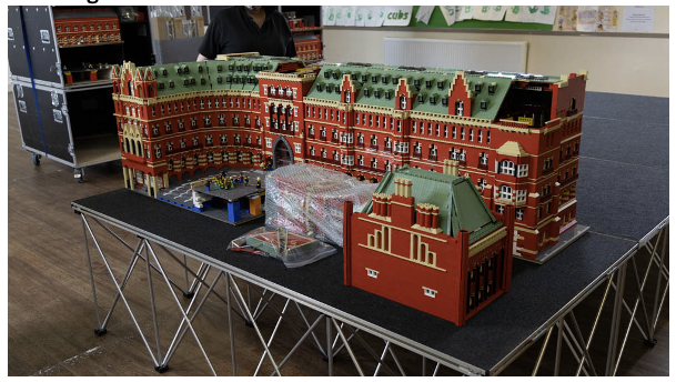
13. You can now adjust the position of the hotel left/right if required.
14. Add the top part ‘penthouse’ to the curved section of the hotel. It doesn’t matter which way round it goes. You may find it easier to do this between two people.
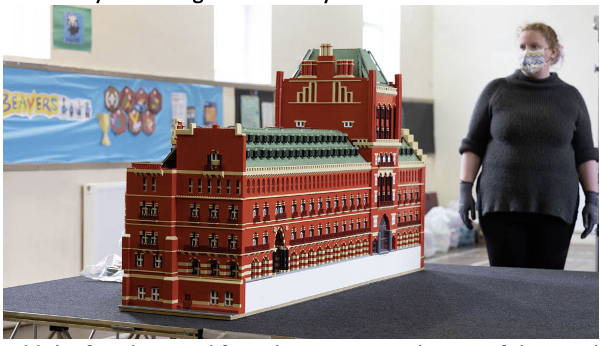
15. Add the four long and four short spires to the top of the penthouse.
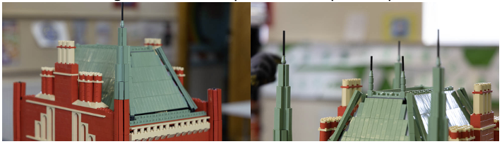
16. Add the two pyramids to the top of the front part of the curved building.
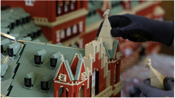
17. Add the statue to the tower in between the pyramids
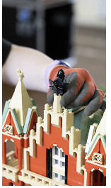
18. Add the clock tower to the end of the straight section of hotel. The two sides with windows face outwards. Check the clock times are correct – and all the same – and add batteries if needed.
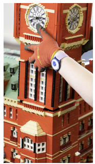
19. Add the top part of the stepped gable end to the end of the straight part (near the clock tower)
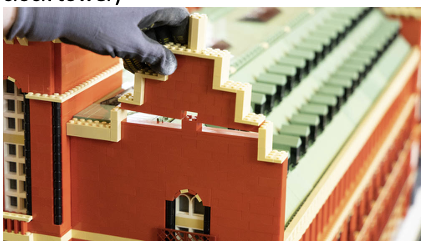
20. Add the chimneys to the hotel building. There are 3 chimney parts marked A, B, C and D which fit onto the curved section – match like to like. Place gently.

21. There are also a number of unmarked chimneys, these fit into the spaces as shown – 2 on the curved section and the remained on the straight section.
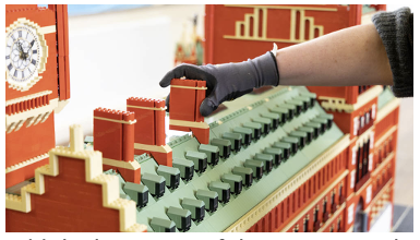
22. Add the large part of the spire onto the clocktower. This is stored in the top right hand section of the wider flightcase. Reattach dragons as necessary.
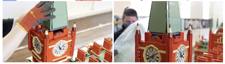
23. Add the small part of the spire, packed in one of the small LEGO boxes, onto the top of the larger part of the spire. This should connect onto the studs.
24. Add the 4 gables to the spire. These are all identical and push into the axle holes until they stop.
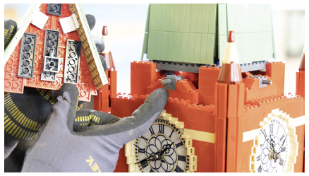
25. Add the front forecourt. This is stored in the top part of the wider case, on the bottom shelf. Slide this towards the completed hotel – it should neatly slide underneath the protrusions on the model to the far right side.
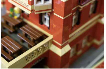
26. Remove the very front piece from the top right of the wider case. This is long and thin, around 75cm wide and 12cm deep. Place this section to the front of the of the model. It should neatly slide underneath the protrusion to the front of the curved section.
27. Add four trees to the road at the front of the building. In the centre of each of the brown squares.
28. Now, start adding the train shed pieces.
29. Start with the first piece – numbered 1. This section is the only one that does not have track running all the way through. Remove this from the case as with the larger sections
30. Add the glass curtain wall to this section before sliding into place. It is the curtain wall piece with the clock included, stored to the top right right of the larger case held in with Velcro straps. The clock faces into the train platforms. Insert the teeth of this piece into the matching holes on the white crossmember. Note that this may be difficult to match up – but is very strong once connected. It is easiest to start at one end and work along. Similarly, lifting the cross member up may be eaiser than pushing the curtain wall down.
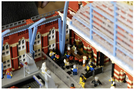
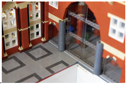
31. Now slide towards hotel. This section should align to the clock tower side of the model (it does not align to the side the curved section is on). The pavements should match up. It should neatly slide underneath the columns near the large archway
.
32. Next, add the next piece – numbered 2. Slide to match.
33. Once this is in place, insert the front nosecone of the train in to match. It is easiest to place it on the track and wheel it back into the rear part.
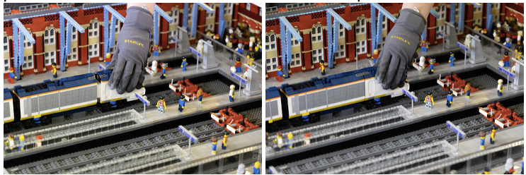
34. Connect the two sections using the red brick with dark gray handles, stored on the track. This connects the two at the top of the wall.
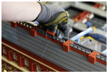
35. Next, add the next piece – numbered 3 in the same way. Bend the canopy outwards and connect as before.
36. Next, add the next piece – numbered 4 in the same way, connecting as before.
37. Finally, add the last piece – numbered 5 in the same way, connecting as before. Also add the glass panel on the opposite side to the walls to connect sections 4 and 5.
38. The two ‘tower’ corners face away from the hotel.
39. Rotate the two blue supports upwards into their correct position – see picture
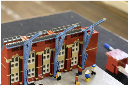
40. Add the white crossmember with red ‘hats’ (stored in the top right part of the wider flightcase) to the end of piece 5. Insert side A first. Feel free to move the bluer arch supports to fit this if necessary.
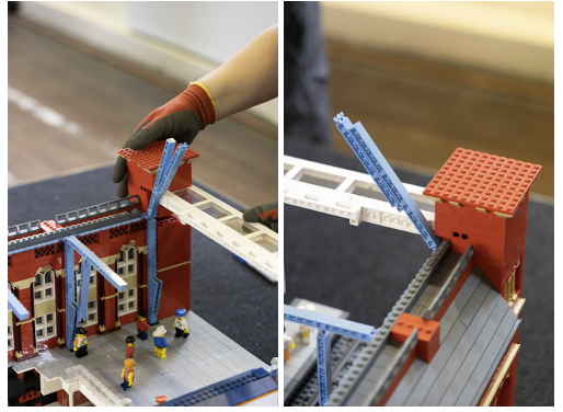
41. Insert the glass curtain wall to the open end of the platforms as with previous curtain wall. The smooth surface should face outwards.
42. The final stage is to add the curved roof trusses. This is much easier with two people, one working on each side.
43. Empty the cardboard tube out onto the deck. There are a number of long blue, flexible pieces. Align all of these so that the yellow marker is at the same end and the studs are all in the same direction. (the long white piece is for the Welcome to Las Vegas sign, not the St Pancras model and can be put to one side.)
44. The one with the white 1x1 plate with clips on goes in last – put this to one side for now.
45. Find the blue piece with 4 white marked studs.
46. Insert the yellow marked end of this piece into the hole at the side of the platform next to the clocktower. Make sure it goes all the way down and the studs face away from the hotel. This goes down further than you think.
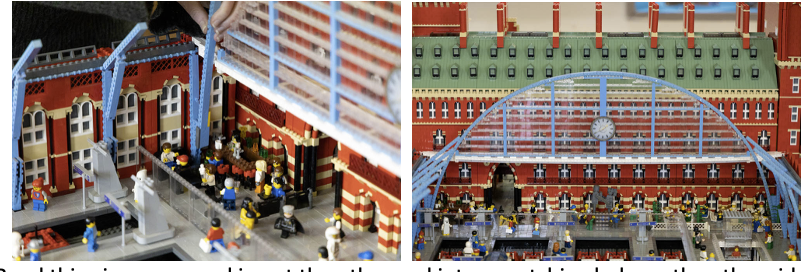
47. Bend this piece over and insert the other end into a matching hole on the other side. This should create an arch which neatly follows the curve of the curtain wall. If not, then it has not been inserted all the way.
48. Repeat for all arches.
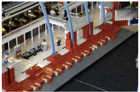
49. Place the last arch (the one with the white protrusions at the end. The protrusions should go upwards.
50. Open the box containing a number of blue ‘sticks’. Find, and put to one side, the four shorter sticks (these have blue dots on their studs).
51. Attach the shorter sticks to the marked studs on the arch placed in section 28. Noting where these connect (see photo), attach between the first and second arch.
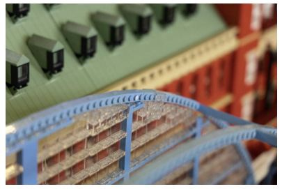
52. Repeat for all ‘sticks’, making sure lines remain straight. You should be able to match a stud pattern as they are all built in the same manner (eg, second stud from left of a 1x4 plate) There should be one spare long stick.
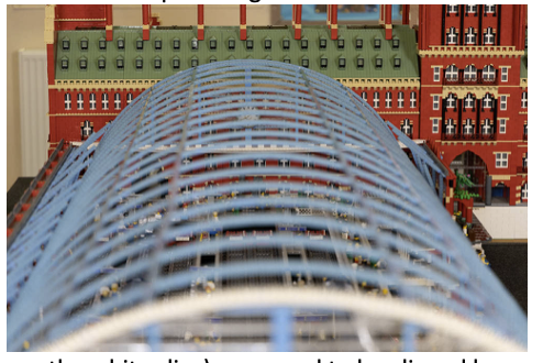
53. The last section (near the white clips) may need to be aligned by eye, rather than matching the stud pattern.
54. Add 4 trans-clear plates to the arch nearest the hotel (stored in the box with the sticks). They should overlap onto the curtain wall to keep everything straight as shown.
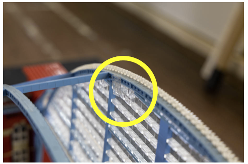
55. Add the chimneys along the side of the train shed.
56. Attach Velcro’d skirt to plinth.
Truss Assembly
If you have not assembled any truss before, please make sure to read the manufacturers instructions (https://globaltruss.de/out/media/download/GT_Manual_multil_V1.1.pdf and also available where you found this document). We use F14 truss for St Pancras.
The only difference to the manufacturers instructions is that where Eggs and pins do not need to be removed – these have been secured with a permanent wire, instead of a pin. DO NOT remove or cut any of these wires, it is not necessary.
All of the truss sections consist of a
· Truss piece (large aluminium cuboid),
· Egg (small aluminium connecting peg piece),
· Pin (even smaller pin that goes through the Egg and truss)
· Cir-clip or wire (which secures the pin from being lost).
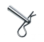
Cir-clip inserted into pin (shown outside of truss for clarity)
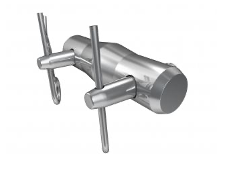
Egg with two pins and circlips connected (shown outside of truss for clarity)
To assemble the truss, you mate a section with Eggs (“A”) to one without (“B”)
· Firstly remove the 4 outer cir-clips and pins from the 4 eggs on the very end of A (but not any Eggs)
· Insert these Eggs into the matching holes on the end of B
· Insert 4 pins from the outside in through the holes of B, the eggs of A, then through the inner holes of B to the inside of the truss
· Secure each pin with a cir-clip into the hole in each pin.
NOT ALL of the truss needs to be disassembled in order to transport the truss. Eggs and pins which do not need to be disassembled are wired permanently in place.
Spares are provided – but you should not need any.
Standard Option
1. Place all six legs (the shortest pieces) as per the diagram.
a. For the standard option, these are pre-connected units. Note that the corner and side legs are different.
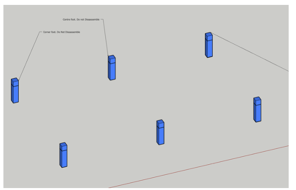
2. Assemble the end trusses onto the corner legs to create 2 wide goalposts.
a. This will be a 1.5m straight WITH eggs and a 1.5m straight WITHOUT eggs.
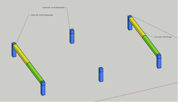
3. Assemble the halves of the long sides, using a 1.5m section WITH eggs and a 1m section WITHOUT eggs. The 1m section should be towards the CORNERS.
4. Attach two of these to each of the end sections. Lower these down onto the ground to help them stay up.
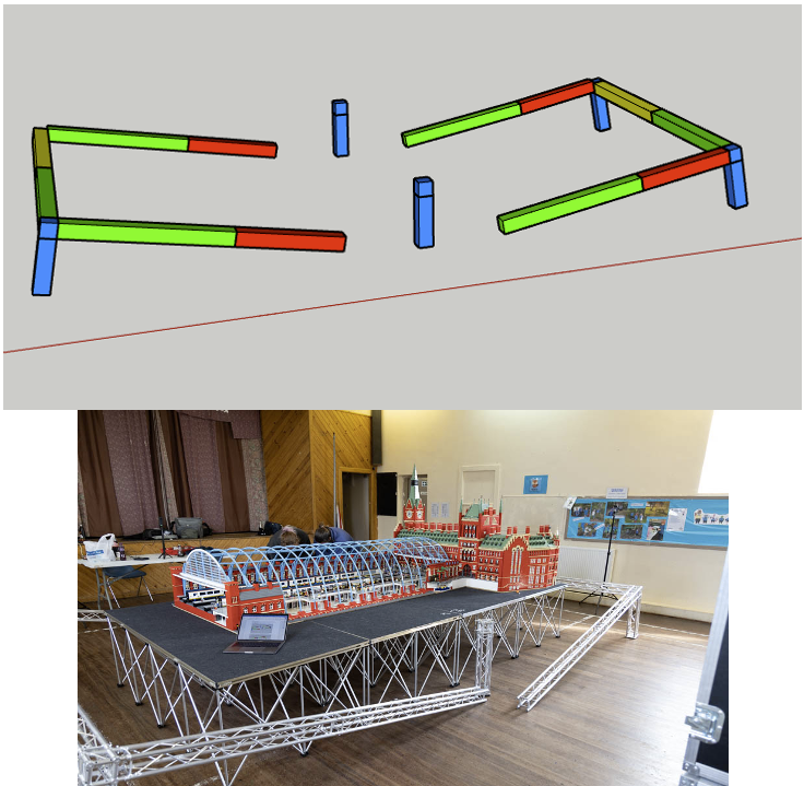
5. Lift each end section up to meet the middle feet and attach.
6. Attach the interpretation brackets to the truss as shown, 2 per short side and 4 per long side. Lower onto the truss so that the brackets connect around the truss – then close clamps and screw finger tight.
It will be necessary to ‘finesse’ the clamps to get a good fit. All wing nuts should be on the inside face of the truss .
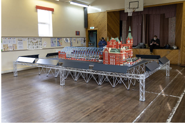
7. Finally, attach the magnetic graphics. They attach as follows;
2 meter Hotel end – ‘Euston Road’ graphic to the left, ‘St Pancras Chambers/Mrs Fawcett/Abandonment’ to the right
4 meter open side – ‘Midland Road’ graphic to the left, then ‘Slum to Station’, ‘WW!’, ‘Regeneration/Eurotunnel’.
2 meter train shed end – ‘Route Map’ (to Glasgow) on the left, ‘Route Map’ (to Europe’ on the right.
4 meter roadway side – ‘Pancras Road’ to the left, then ‘1868-1922’, ‘1935-1960s’, .1970s – 2018’.
Packing and dissassembly
Packing is the reverse of assembly.
